Decoded USB C Wiring Diagrams and Color Code Analysis.
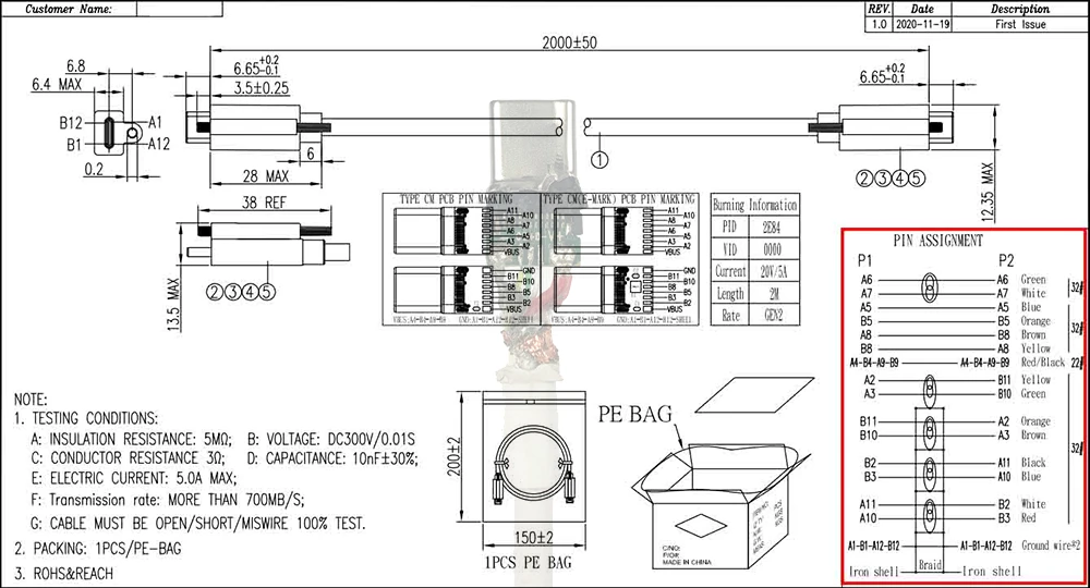
USB-C has become the go-to connector for modern devices, offering faster data transfer speeds, versatile power delivery, and a reversible design. However, understanding the intricate wiring behind this compact powerhouse can be a daunting task.
We will explore the physical construction of USB-C cables, connectors, and ports, different connections wiring diagrams. Accompanied by detailed diagrams, this article will unravel the complexities of USB-C wiring, empowering you to make informed decisions when selecting cables and devices. Get ready to unlock the full potential of USB-C as we embark on this enlightening journey together.
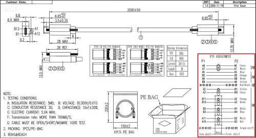
USB C To USB C Wiring Diagram.
The realm of USB technology is constantly evolving, bringing forth a multitude of connectors, cables, and communication protocols. Within this intricate network, the USB Type-C connector stands out as a versatile and universally adopted interface. It’s crucial to understand the wiring and communication protocols, as they dictate how our devices interact and transfer data. The USB 3.1 Gen 1, originally known as USB 3.0, is at the heart of USB-C technology. This is essentially a renaming of the existing USB 3.0 specification, bringing us a step closer to the universality of USB-C.
One of the key features of USB-C is its backward compatibility. All USB 3.0/3.1 Gen 1/3.2 Gen 1×1 devices share the same hardware interface and USB protocol. This compatibility extends to USB Type-C to USB-A Male 3.1/3.2 Gen 2 Adapter charger cables, which support data transfer rates of up to 40Gbps.
The unique feature of USB-C lies in its reversibility. A look at the pinout diagram of the USB-C male connector reveals that pins labeled as “A” can be interchangeably used with those labeled as “B.” This design is highly convenient and adds to the user-friendliness of USB-C connectors. Pin positions with the same function are in a symmetrical array relative to the center point. When the C male connector is inserted into the C female connector, the pins function as a perfect fit regardless of the insertion direction. Moreover, the power supply VBUS/GND has 4 pins, and these 4 pins can supply power at the same time. This is the main reason why USB C is different from previous connector ports and can achieve high current of 5A. The detailed USB C pin array can be found in our corresponding knowledge base.
We understand that ordering custom USB cables in bulk is a big move related to business development. Therefore, we have partnered with Amazon Retail to create a trial event where you can use the discount code (QNPRPWAI) to order a small number of USB C cables with USB2.0 data transmission standard PD3.0 fast charging protocol at a super low price.
*This discount is an exclusive discount for bulk customers to obtain samples, helping B-end customers reduce upfront costs and shipping time. Please don’t spread it around.
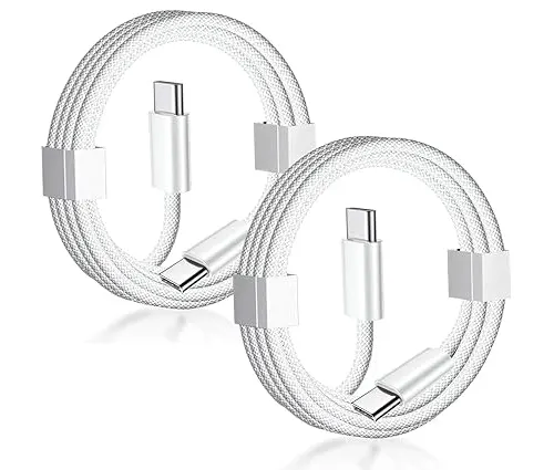
Hopefully this event will allow you to experience and purchase USB C to C cable samples at a very low price. Unpack our ordinary nylon braided USB C cable and evaluate our USB C wiring method. If you have custom transmission requirements for USB C cables, but you are not sure how to configure the pins and copper wire specifications for wiring. Please contact us, our experienced team of engineers are fully capable of customizing according to your needs.
Color Codes for USB C Wiring.
With the advent of USB 3.X and its significant speed enhancements, USB Type-C cables now incorporate an additional five wires featuring two pairs, one for transmission (TX) and one for reception (RX). These pairs include TX+ and TX-, as well as RX- and RX+, along with an extra ground return.
The challenge lies in distinguishing these five new connections, and this led to the introduction of new USB C wire color codes for these wires, while still maintaining compatibility with existing USB 2.0 wires. USB 2.0 and 3.0 “type A” connectors are interchangeable without any compatibility issues.
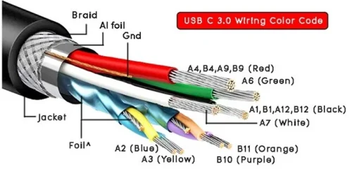
The following image displays the USB C Type-C cable color codes, along with signal names at the USB C plug:
Please note that some cables may contain blue-colored Mylar material foil with a conducting inner layer, though its presence is optional and does not violate USB protocol; these are independent grounds connected at the end.
| USB type c wire color table/port USB C color code | ||
|---|---|---|
| Conductor Color | Pins At Port | Signal Name |
| Red | A4,B4,A9,B9 | VBUS |
| White | A7 | Dn1/ D- |
| Green | A6 | Dp1/ D+ |
| Black | A1,B1,A12,B12 | GND |
| N/A | A5 | CC |
| N/A | B5 | VCON |
| Blue | A3 | TX1- |
| Yellow | A2 | TX1+ |
| Purple | B10 | RX1- |
| N/A | GND | GND |
| Orange | B11 | RX1+ |
| N/A | SHELL | SHIELD |
Now, let’s break down the color codes for the specific wires:
- A6 and A7 (Differential Data Lines): These wires serve as data lines (D+ and D-) for USB 2.0 connections. A6 is typically green, and A7 is white, and they usually form an unshielded pair of wires.
- A4, B4, A9, B9 (VBUS – Power Supply): This wire, responsible for power supply, is color-coded red. All these pins share a common terminal at the end.
- A1, B1, A12, B12 (GND – Ground): Another power supply wire, it is color-coded black, and similar to VBUS, these pins are common at the terminal end.
- B10 and B11 (RX1- and RX1+ – Data Receive): These wires are a shielded pair responsible for high-speed data reception. B10 is purple, and B11 is orange. They are typically shielded with conducting foil, often made of aluminum material. If there is an extra conductor with this pair, it serves as an additional ground.
- A2 and A3 (TX1- and TX1+ – Data Transmit): A2 is blue, and A3 is yellow, and these wires represent a shielded pair for high-speed data transmission. Similar to RX1- and RX1+, they are shielded with conducting foil, commonly made of aluminum. As with the previous pair, any additional conductor is used as a ground. The shield is grounded at both ends.
It’s important to note that the mentioned color codes conform to USB Type-C standards, but variations might exist, and some manufacturers could use different color schemes in their USB Type-C cables. While VBUS, GND, D+, and D- typically have fixed color codes adhered to by most manufacturers, other signals may have varying color combinations. For instance, TX1+ and TX1- or RX1+ and RX1- could appear in black and white colors, albeit within a different color jacket or Mylar foil.
Understanding these color codes is essential when working with USB Type-C connectors and cables, as they play a vital role in ensuring proper connectivity and data transmission.
At APPHONE offers a wide range of high-quality USB Type-C cables, adhering to the standards and color codes, to guarantee reliable and efficient connectivity in your devices. Explore our selection here.
USB C To USB A Wiring Diagram
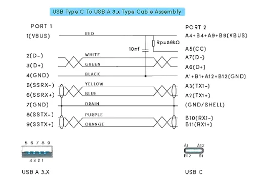
USB C To USB A 3.X Wiring Diagram:
| Signal Name | Port 1 | Conductor Color | Port 2 | Signal Name |
|---|---|---|---|---|
| VBUS | 1 | RED | A4,B4,A9,B9 | VBUS |
| D- | 2 | WHITE | A7 | Dn1/ D- |
| D+ | 3 | GREEN | A6 | Dp1/ D+ |
| GND_DRAIN | 4 | BLACK | A1,B1,A12,B12 | GND |
| N/A | – | N/A | A5 | CC |
| N/A | – | N/A | B5 | VCON |
| SSRX- | 5 | BLUE | A3 | TX1- |
| SSRX+ | 6 | YELLOW | A2 | TX1+ |
| SSTX- | 8 | PURPLE | B10 | RX1- |
| GND_DRAIN | 7 | – | GND | GND |
| SSTX+ | 9 | ORANGE | B11 | RX1+ |
| SHIELD | SHELL | N/A | SHELL | SHIELD |
- In accordance with USB standards, the VBUS line carries a voltage of +5V and can deliver an output current of up to 3.0A.
- Pin number 1 of the USB Type A 3.1 male connector corresponds to Pin numbers A4, A9, B4, and B9 of the USB Type C. This pin, denoted as (+VDD/VBUS), serves the dual purpose of supplying power to the connected device and acting as an indicator for a successful handshake signal, signaling that the device is successfully connected.
- For Pin number 4 on (Port1) USB Type A 3.1 male, it connects to Pin numbers A1, A12, B1, and B12 on (Port2) USB-C, representing the ground return (GND) with a distinctive black-colored wire.
- Pin number 3 of the USB 3.1 Type A male links to Pin number A6 on Port 2.
- Pin number 2 from the USB Type A male connector connects to Pin number A7 on Port 2. Both Pin number 2/A7 (D-) and Pin number 3/A6 (D+) serve as differential data pins for each port, facilitating data transmission in USB 2.0 mode when used in reverse compatibility mode with previous-generation USB hosts.
- Pin 7 is utilized as a Drain/Shell connection.
- Pin number 5 (SSRX-) from Port 1 is connected to Pin number A3 (TX1-) of Port 2, while Pin number 5 (SSRX+) from Port 1 is linked to Pin number A3 (TX1+) of Port 2. These connections represent bidirectional data SuperSpeed Transmitter ends. Note that SSRXp1 can be expressed as SSRX1+ and SSRXn1 can be represented as SSRX1-.
- Similarly, Pin number 8 (SSRX-) from Port 1 is linked to Pin number B10 (RX1-) of Port 2, and Pin number 9 (SSRX+) from Port 1 is connected to Pin number B11 (RX1+) of Port 2. These connections also represent bidirectional data SuperSpeed Transmitter ends. Note that SSTXp1 can be written as SSTX1+ and SSTXn1 can be expressed as SSTX1-.
USB A to USB C 2.0 Wiring charging:
| Pin no. at USB A | Pin no. at USB C | Wire code | Description | Symbol |
|---|---|---|---|---|
| 1 | A4, B4, A9, B9 | Red | +5V (dc power) | VCC/VBUS |
| 2 | A7 | White | Data- (data from device to host) | D- |
| 3 | A6 | Green | Data+ (data from host to device) | D+ |
| 4 | A1, B1, A12, B12 | Black | 0V (dc ground) | GND |
| NC | A5* | – | Configuration Channel 1 (VBUS through resistance Rp =5.6kΩ) | CC1 |
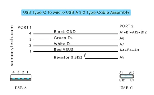
The provided USB C wiring diagram illustrates the assembly diagram for a “USB Type C to USB 2.0 type cable.” Both USB charging cables and USB OTG cables share the same assembly diagram, differing only in terms of their ports. Specifically, USB 2.0 type A male and female connectors have the same wiring configuration, with the distinction lying in the port itself.
In practical terms, this means that one end of the cable is standardized, featuring the USB C port, while the other end can take one of two forms: USB A male or USB A female connectors. These two variations serve different purposes, with one being a USB charging and data cable, and the other serving as a USB OTG cable, facilitating On-The-Go connectivity.
Within the internal wiring diagram of a USB A to USB C 2.0 charging and data cable, it’s essential to note the significance of pin A5 (CC), which is connected in series with a resistor marked as Rp, featuring options like 5.1kΩ, 5.3kΩ, or 5.6kΩ. The specific value of Rp is pivotal as it determines the cable’s or device’s current-carrying capacity for which it is designed.
For high-quality USB cables, it is strongly recommended to incorporate internal shielding for all wires, ensuring 360-degree shield termination at both cable ends. This shielding, known as SHELL, SHIELD, or BRAID, consists of conductive material and is grounded at both terminations. The primary purpose of this shielding is to effectively ward off undesirable RF interference and noise signals, thereby enhancing cable performance.
USB C To HDMI Wiring Diagram
The USB Type-C to HDMI connection involves intricate pin mapping and hardware components, allowing for the transmission of HDMI signals. HDMI Type-A and USB Type-C connectors are utilized to achieve this connection. The following details provide a comprehensive understanding of this connection.
HDMI Pin Mapping.
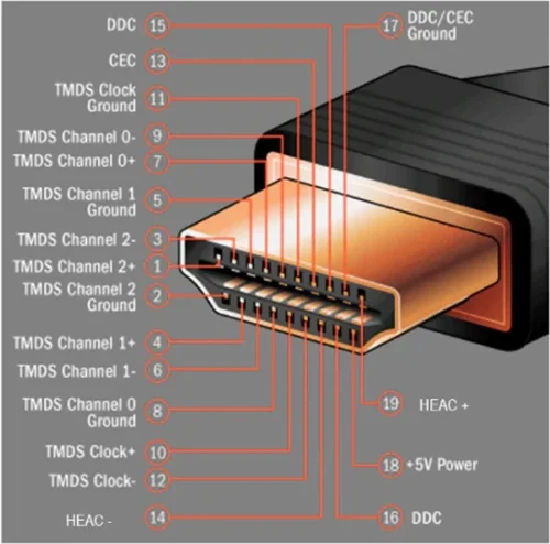
The standard HDMI Type-A connector comprises 19 pins, including three high-speed data channels transmitted as shielded twisted pairs. In the Figure below, you can observe the HDMI Type A connector, which features three TMDS pairs and their clock signal.
As you can see the HDMI Type A connector has 19 pins. Also, it includes three high-speed data channels as shielded twisted pairs
Below , you can see the pin mapping for HDMI in USB Type-C Alternate Mode. This mapping is essential for connecting HDMI signals through a USB Type-C port.
Initializing HDMI Alternate Mode.
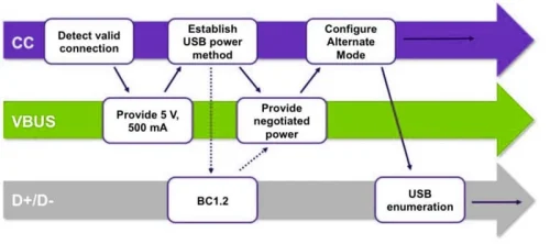
The USB Power Delivery (USB PD) specification defines the sequence of events necessary to initiate the HDMI Alternate Mode. When connecting a USB PD-enabled Type-C cable between two ports, negotiations occur over the CC line. These negotiations establish the use of USB or Alternate Mode and identify the specific Alt Mode standard.
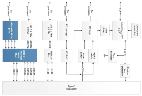
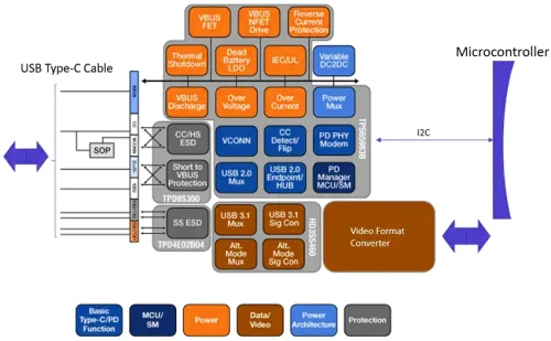
To add HDMI functionality to a USB Type-C port, specific hardware components are required, as depicted in the below figure. These components include the Alternate Mode Physical Layer Device (PHY), the Alternate Mode Multiplexer (MUX), and the USB PD PHY and PD manager.
While dedicated chipsets for HDMI Alt Mode are still in development, DisplayPort Alt Mode parts can be utilized by incorporating an HDMI format converter. The design relies on components like the Texas Instruments’ TPS65982 USB Type-C and PD controller and the HD3SS460 high-speed multiplexer/demultiplexer. Additionally, a video converter is used to switch between DisplayPort and HDMI formats.
This implementation highlights the complexities and considerations involved in establishing HDMI Alternate Mode through a USB Type-C connection, allowing users to transmit HDMI signals with reliability and quality.
USB C To Micro Wiring Diagram
The micro USB connector has been widely used for charging mobile phones and portable devices due to its compact design. Some manufacturers create charging-only cables by excluding the data pins to reduce costs.
- In terms of connections, pin no.1 from a micro USB male connector is linked to pins A4, A9, B4, and B9on the USB C end. This pin serves as the power supply, denoted as (+VDD/ VBUS). It isresponsible for delivering power to the connected device and acts as an indicator for the handshake signalsignifying that the device is successfully connected.
- Additionally, pin no.2&3 from the micro USB male is connected to pin A6&A7 on the USB C end. BothPin no. 2/A7 (D-) and pin no. 3/A6 (D+) are utilized as a differential data pin in each port, with datatransmitted andreceived following the USB protocol.
- Micro USB pin 4 supports CBUS: hot plug.
- Furtherm ore, pin no.5 from the micro USB male is connected to pins A1, A12, B1, and B12 on the microUSB C end. designated as the ground supply (GND) responsible for establishing a ground connection.
While micro USB has been dominant, a newer and more advanced version called USB-C has emerged. USB-C offers reversible insertion, allowing the connector to be plugged in from any orientation. This is a significant improvement compared to the directional nature of micro USB.
USB C To AUX Wiring Diagram
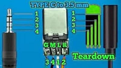
USB-C to AUX adapters or cables are used to connect devices with a USB-C port, such as smartphones or laptops, to audio devices with an AUX (3.5mm) port input, like headphones or speakers.
The USB-C connector has multiple pins, but for audio transmission, it primarily utilizes the analog audio pins. The wiring diagram for a USB-C to AUX cable typically involves connecting the corresponding pins of the USB-C connector to the appropriate contacts of the AUX connector.
USB-C Connector:
- VBUS (Power): This pin carries the power supply for the AUX device.
- GND (Ground): This pin is connected to the ground of both the USB-C and AUX connectors.
- CC (Configuration Channel): This pin is responsible for identifying the type of device connected and negotiating power delivery.
- D+ and D- (Data): These pins are typically not used for audio connections but are essential for data transfer in USB-C cables.
AUX Connector:
- Connect the AUX Ground contact to the USB-C Ground pin.
- Connect the AUX Left Audio contact to the USB-C Left Audio Out pin.
- Connect the AUX Right Audio contact to the USB-C Right Audio Out pin.
USB C To VGA Wiring Diagram
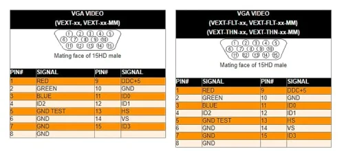
USB-C is a digital interface, while VGA is an analog video format. Therefore, a direct physical wiring diagram for USB-C to VGA conversion does not exist.
To connect a USB-C device to a VGA display, you will need an active USB-C to VGA adapter or cable. These adapters incorporate electronics to convert the digital signal from the USB-C port to an analog VGA signal.
The adapter or cable will have a USB-C connector on one end, which plugs into the USB-C port of your device, and a VGA connector on the other end that connects to the VGA input of your display. The conversion process happens within the adapter or cable itself.
Understanding the USB-C wiring diagram is essential for anyone dealing with modern technology. Whether you’re an enthusiast, a DIYer, or a professional, comprehending the intricate web of wires and connections within the USB-C type cable can help you troubleshoot, repair, and innovate. USB-C’s universal appeal and the power it delivers in terms of data transfer, charging, and connectivity continue to shape the future of our digital world.
For reliable and certified USB-C cables, connectors, and other high-quality accessories, you can turn to Apphone. As an MFI Certified Professional USB-C Cable Manufacturer, Apphone is dedicated to providing top-notch products that meet rigorous standards and ensure compatibility with your Apple devices. With a commitment to quality and innovation, Apphone is your trusted partner in the ever-evolving world of USB-C technology.
Visit Apphone’s website to explore their range of USB-C products and discover how our expertise can enhance your USB-C experiences. Your USB-C journey is in good hands with us, Get a Quote Today.

Fast delivery
Fastest delivery within 22 days

Quick proofing
Fastest 3-day proofing cycle

After-sale protection
24-month long warranty

1V1Customer Service
Professional customer service follow-up

