USB C Pinout names and functions you need to know.
Have you ever marveled at the sleek, reversible design of a USB Type-C connector? This article embarks on an exploration of the usb type c pinout, unraveling its intricate details and multifaceted capabilities.
USB Type-C, a revolutionary specification for connector systems, has surged in popularity, becoming a staple in the world of smartphones and mobile devices. Beyond its impeccable design, it’s a powerhouse that seamlessly integrates power delivery protocol and high-speed data transmission.
Bid farewell to the days of frustrating plugging attempts, for the USB Type-C connector is delightfully flippable. No more wrestling with orientation; it effortlessly slides into place. But there’s more to USB Type-C than its convenience – let’s dive deeper into its inner workings.
USB C Connector Overview.
USB-C, also known as USB Type-C, is not just a connector but a technological marvel that has replaced its predecessors. It’s a versatile gateway that carries audio and video data, facilitates data transfers, and delivers power, all while being adopted by various protocols like Thunderbolt, PCIe, HDMI, DisplayPort, and more. This 24-pin connector brings a level of flexibility that’s unparalleled. Its adaptability ensures compatibility with evolving USB standards. Currently unparalleled, USB-C is the go-to interface, poised to retain its significance as the universal connector for diverse devices. It serves as a universal interface, ensuring connectivity and data transfer efficiency, making it the go-to choice for modern technology.
- One of the most remarkable features of USB-C is its reversibility. Unlike older USB connectors that had specific host and peripheral ends, USB-C can connect in any direction. It’s like a universal key that fits any lock, making it incredibly convenient for users. The “C” in USB-C stands for its form factor, distinguishing it from the previous Type-A and Type-B connectors. Don’t let the name fool you; USB-C’s capabilities go far beyond its label.
- Thanks to the multitude of supported protocols by both host and peripheral devices, a USB-C connection offers significantly higher data rates compared to its predecessors. It’s a true powerhouse, capable of handling Thunderbolt 3, DisplayPort 2.0, or USB 3.2 Gen 2×2, depending on the connected devices’ capabilities.
- What sets USB-C apart from its forerunners is its rotational symmetry. No more fumbling to insert the plug in the right direction; it goes in either way with ease.
What is a USB C Pinout?
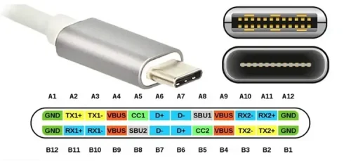
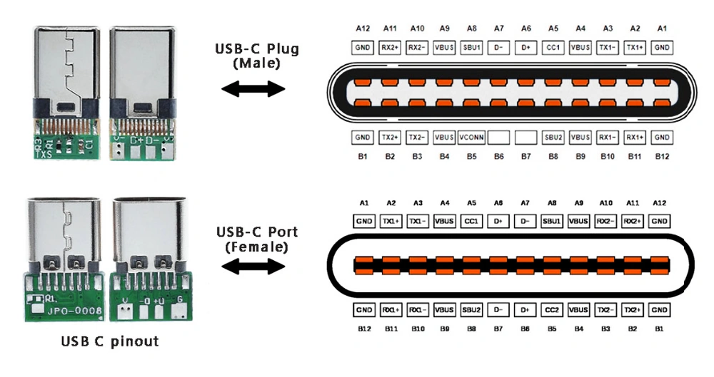
The USB Type-C connector has 24 pins. From the USB C pinout diagram at the top, you can see USB connectors configured for USB 2.0 mode, utilizing pins like D+, D-, VBUS, and GND. It’s worth noting that USB 3.0 involves fully functional cable connections with 8 to 10 connecting wires or buses.It features a 24-pin double-sided connector with specific measurements: 8.4mm in width, 2.6mm in height, and a depth of 6.65mm.
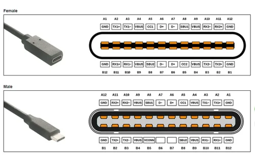
These dimensions are important to note for both the internal side of a receptacle and the outer side of a plug, ensuring a secure and functional connection. The USB-C connectors come in two primary forms: male plugs and female receptacles. Male plugs are commonly found on cables and adapters, serving as the connecting end for various devices. In contrast, female receptacles are typically integrated into devices and adapters, offering a socket where the male plug is inserted to establish connections.
Development History:
The roughly the usb type c specification 1.0, published by the USB Implementers Forum (USB-IF) in August 2014, paved the way for this incredible technology. It was introduced alongside the USB 3.1 specification and later adopted by the International Electrotechnical Commission (IEC) as “IEC 62680-1-3” in July 2016.
It’s worth noting that not every device with a Type-C connector implements USB transfer protocols, USB Power Delivery, or Alternate Modes. While the Type-C connector is common to multiple technologies, not all are mandatory.
In 2017, USB 3.2 took over from the USB 3.1 specification. It retained the SuperSpeed and SuperSpeed+ data transfer modes while introducing two additional modes with signaling rates of 10 Gbit/s and 20 Gbit/s. These modes require Full-Featured USB-C connectors and usb type c cable on both ends to unlock their full potential.
Finally, in 2019, USB4 emerged as the first USB transfer protocol exclusively available via USB-C. With USB4, the future of connectivity is even more promising.
USB C Connector Applications:
In the realm of power applications, the USB Type-C connector emerges as a game-changer, boasting a total of 24 pins, including 16 for data transfer, 4 for power, and 4 for grounding. With the capacity to deliver up to 240 W of power, USB Type-C has become a compelling choice for numerous power-hungry applications. What sets it apart is not just its power capabilities but its versatility, making it a viable replacement for traditional DC power connectors, even in scenarios where data transfer isn’t a requirement. Here are some common applications of type C connector:
- Laptops and Notebooks;
- Personal Computers;
- Tablets and Portable Music Players;
- Printers and Scanners;
- Digital Cameras;
- LCD and LED Monitors;
- Set-Top Boxes;
- Mobile Handsets;
- Factory Automation;
- Medical Devices;
- Data Centers;
- Power Packs and Chargers;
- Lighting Systems;
- Industrial Machinery;
From an original equipment manufacturer (OEM) perspective, USB Type-C connectors, whether for power-only or data-and-power applications, offer ready availability with a highly stable supply chain. Standardization ensures a certain level of interoperability, simplifying design integration. Moreover, USB Type-C boasts a compact footprint, outperforming many traditional barrel connectors in this regard. As a final testament to its excellence, these connectors are built to last, with a robust rating of 10,000 mating cycles, ensuring a long and productive lifespan.
USB C Connector Features:
The USB-C connector is characterized by several key features that set it apart in the world of connectivity:
- Reversible Connector:The USB-C connector boasts a unique reversible design, allowing users to insert it into the type c receptacle data transfer in either orientation. This eliminates the frustration of trying to plug it in the right way and enhances user convenience.
- Multi-Protocol Support:USB-C is a versatile interface that can accommodate a range of USB standards, including USB 2.0, USB 3.0, USB 3.1 Gen 2 and USB 4. What’s more, it goes beyond USB standards and supports third-party protocols like DisplayPort and HDMI through a feature known as Alternate Mode. This versatility enables USB-C to handle various data transfer and display needs seamlessly.
- High Data Transfer Speed:USB Type-C offers remarkable data transfer rates of up to 5~40 Gb/s, ensuring swift file transfers and efficient data access.
- Robust Current Handling:With the capacity to handle currents of up to 5 Amps, USB-C supports power-hungry devices while maintaining performance.
- Compact Design:Its small form factor, akin to USB 2.0 micro-B connectors, optimizes space utilization in devices while maintaining functionality.
- 4K Video Output:USB-C can replace traditional video ports like VGA and HDMI. Especially after incorporating Thunderbolt technology, it provides stunning ultra-high-definition (4K) video quality, bringing an immersive gaming and cinema experience.
- High-Quality Audio:It can also replace traditional audio outputs, like the 3.5mm headphone jack, ensuring high-quality audio and music reproduction on smartphones and tablets.
- Fast Internet Connectivity:USB-C’s versatility extends to replacing Ethernet ports, providing high-speed internet connectivity with speeds of up to 1000 Mb/s.
- Power Negotiation:One of the standout features of USB-C is its ability to adjust power flow with support for PD and QC fast charging protocols. Devices connected via QC USB-C can communicate and determine the most appropriate power level required. This is especially valuable for charging, as it ensures the device receives the right amount of power, preventing overcharging and maximizing efficiency.
In addition to these core features, USB-C connectors are known for their robustness, with a high mating cycle rating, and their compatibility with a wide range of devices. These features collectively make USB-C a leading choice for modern connectivity solutions across various applications.
Differences Between USB C Male and Female USB C pinout.
Male and female connectors exist for various types of Universal Serial Bus jacks, including the Micro USB-B male connector and USB-A female connector. This gender differentiation is necessary because you always need two components with opposite genders to create a connection, regardless of the specific USB type.
Additionally, adapters and converters with various gender configurations are available for different generations and types of USB connectors, such as male-to-male, female-to-female, male-to-female, and female-to-male USB ports.
A female USB connector, often referred to as a port, slot, receptacle, or socket, is commonly found on host devices and hubs. It allows external USB devices and peripherals to be plugged in.
On the other hand, the male USB connector, commonly known as a plug, is typically located at the end of a cable or can be physically attached to smaller accessories like USB memory sticks. This plug inserts into the female port, which is typically found in the casing of larger devices.
The symmetrical arrangement of pin positions around the center point is evident. When the male connector is plugged into the female connector, the pin functions align perfectly regardless of the insertion direction. Furthermore, both VBUS and GND power supply lines consist of 4 pins, enabling simultaneous power delivery from all 4 pins. This key feature sets USB-C apart from previous connectors and facilitates its capability to support high currents of up to 5A.
| USB C Pinout Table | |||||
|---|---|---|---|---|---|
| Description | Signal A | Pin | Pin | Signal B | Description |
| Ground | GND | A1 | B12 | GND | Ground |
| SuperSpeed differential pair 1 TX, positive | TX1+ | A2 | B11 | TX1+ | SuperSpeed differential pair 1 RX, positive |
| SuperSpeed differential pair 1 TX, negative | TX1- | A3 | B10 | TX1- | SuperSpeed differential pair 1 TX, negative |
| Bus Power | VBUS | A4 | B9 | VBUS | Bus Power |
| Configuration channel | CC1 | A5 | B8 | SBU2 | Sideband use |
| USB 2.0 differential pair, position 1, positive | D1+ | A6 | B7 | D2- | USB 2.0 differential pair, position 2, negative |
| USB 2.0 differential pair, position 1, negative | D1- | A7 | B6 | D2+ | USB 2.0 differential pair, position 2, positive |
| Sideband use | SBU1 | A8 | B5 | CC2 | Configuration channel |
| Bus Power | VBUS | A9 | B4 | VBUS | Bus Power |
| SuperSpeed differential pair 2 RX, negative | RX2- | A10 | B3 | TX2- | SuperSpeed differential pair 2 TX, negative |
| SuperSpeed differential pair 2 RX, positive | RX2+ | A11 | B2 | TX2+ | SuperSpeed differential pair 2 TX, positive |
| Ground | GND | A12 | B1 | GND | Ground |
USB Type C Connector Pin Function Definition.
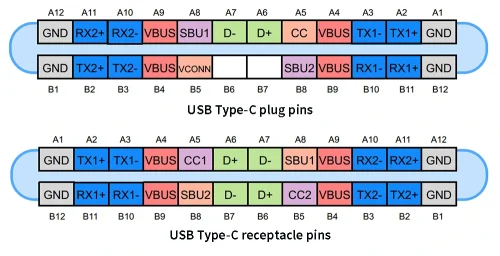
The USB Type-C connector has 24 pins and the image below shows the pins of the USB Type-C receptacle and plug.
USB 2.0 Differential Pairs
For USB 2.0 connectivity, the D+ and D- pins consist of two pairs each within the receptacle. However, these pairs are interconnected, offering just one usable USB 2.0 data differential pair. This redundancy enables the reversible nature of the connector.
Power and Ground Pins
The VBUS and GND pins serve as the power supply and return paths for signals. The default VBUS voltage is 5 V, but devices can negotiate and opt for an alternative VBUS voltage as per the standard, supporting up to 48 V. The maximum current can also be raised to 5 A, allowing the USB Type-C to deliver a maximum of 100~240W of power.It uses a buck-boost converter to provide the required voltage.
Notably, the power delivery technology enhances the versatility of USB Type-C, accommodating varying power requirements for devices. This means you can use the same cable to charge both your smartphone and notebook.
RX and TX Pins
Two sets of RX and TX differential pairs are available. One of the RX pairs, along with a TX pair, can be employed for USB 3.0/3.1 protocol. Since the connector is reversible, a multiplexer is necessary to correctly route data via the cable.
It’s important to mention that a usb type c port can support USB 3.0/3.1 standards, but the basic USB Type-C feature set does not inherently include USB 3.0/3.1. In such cases, the RX/TX pairs can be utilized for other USB Type-C functionalities like Alternate Mode and USB Power Delivery, possibly using all available RX/TX differential pairs.
CC1 and CC2 Pins
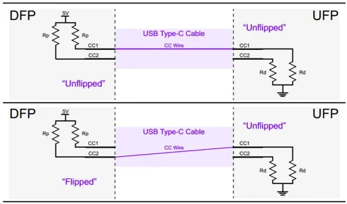
CC1 and CC2 pins, also known as Channel Configuration pins, serve various functions, including cable attachment and removal detection, receptacle/plug orientation detection, and current advertisement. These pins can also facilitate the communication required for Power Delivery and Alternate Mode.
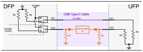
Image above illustrates how CC1 and CC2 pins reveal the receptacle/plug orientation, with DFP (Downstream Facing Port) and UFP (Upstream Facing Port) denoting their roles.
When a USB Type-C cable is connected, it creates a current path between the 5 V supply and ground, enabling the determination of USB C cable pinout attachment and orientation by monitoring the voltage on the DFP CC1 and CC2 pins. Additionally, the Rp-Rd path is used to communicate the source’s current capabilities, with different voltages indicating varying power levels.
VCONN Pin
To support high speed data transfer and power flow, special cables with electronic marking may be needed, along with active cables that incorporate re-driver chips to strengthen signals. To power the circuitry within these cables, a 5 V, 1 W supply can be applied to the VCONN pin, as depicted in below Image.
Active cables employ Ra resistors to pull down CC2 pins, allowing the DFP to determine cable orientation while delivering power to the relevant circuitry inside the cable.
SBU1 and SBU2 Pins
The SBU1 and SBU2 pins are low-speed signal paths exclusively used in the Alternate Mode.
How are the pins of the USB C cable connected?
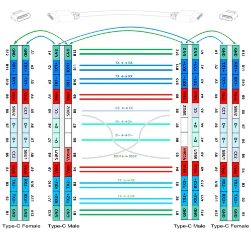
The connection diagram of the full-featured USB-C to USB-C Gen 2 cable is as follows.
USB C cable pin mirroring relative connection principle:
The above figure shows the connection of each pin from the left USB port socket to the right port in the mirrored connection state of the two sides of the USB C cable: D+ is connected to D+, D- is connected to D-; RX1 pairs are matched with RX1 pairs, RX2 pairs are matched with RX2 pairs; SBU1 is connected with SBU2, and CC1 is connected with CC1.
In a regular USB C cable, the VCONN pins at both ends do not need to be connected (B5). When the USB C cable has an electronically marked (E-mark) chip, B5 of the left plug and B5 of the right plug can be connected to each other to provide high-speed data and power transmission.
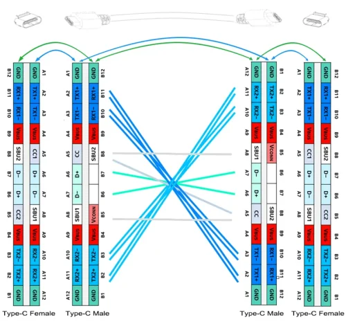
Principle of same-direction connection of USB C cable pins:
When the two ports to be connected to the USB cable remain unchanged, the connector at one end of the USB C cable is flipped (USB-C supports forward and reverse insertion). In this case, the pin connections from the left and right are: the RX1 pin pair is connected to the TX2 pin pair, the RX2 pin pair is connected to the TX1 pin pair, and high-speed data is transferred through the RX1+/- and TX1+/- on the left to the TX2+/- and RX2+/- on the right. The two pairs of USB2.0 differential pairs D+ and D- remain unchanged, SBU1 is connected to SBU1, SBU2 is connected to SBU2, and CC1 is connected to CC2 through the CC line.
The pins at both ends of the USB C to C cable are cross-interchangeable. No matter how it changes, there are only two ways of connection: through (turning both ends at the same time equals through) and cross-pass (one-way flipping).
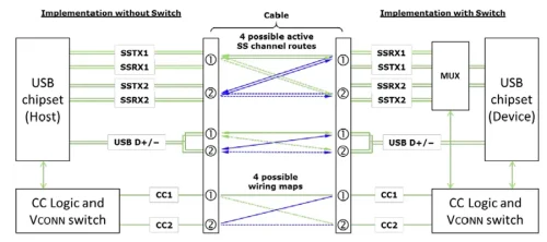
So in a 3.1 USB-C to USB-C cable, you can see four pairs of high-speed signal pairs. Normally there are only two pairs working. If the single-ended plug is reversed, the other two pairs of idle signal pairs can replace the original working pairs. In addition, when the power supply or data transfer of the host and peripheral functions changes, the signal pairs will also continuously switch to distribute the signal connection.
In USB 3.2 dual-channel high-efficiency transmission, a multiplexer must be used to configure the RX/TX data pair for each possible connection state in order to establish correct communication. The diagram below shows the data pair routing capabilities between USB Type-C ports, by measuring CC1/CC2 (channel configuration pins) on each terminal you know the direction of the plug and socket, then the CC logic controller can complete the mux routing setup in the mux or USB chipset.
3.0/3.1/3.2 are essentially the same USB standard, but the USB-IF renames the strategy adjustment. If you are confused, you can go to our related blog to learn more.
USB 2.0 VS 3.x Series Modules.
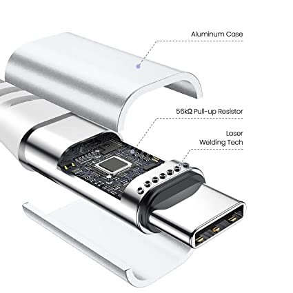
USB 2.0 and USB 3.x series modules offer different capabilities and features. USB 2.0 utilizes a simpler pinout configuration and supports basic differential pair topology. However, when using USB-C with USB 2.0, an adapter is required due to the differing pin count and receptacle/plug mating. It’s important to note that mismatched pull-up resistors can cause power-related issues and potential damage to devices.
| Pin Des | A1 | A2 | A3 | A4 | A5 | A6* | A7* | A8 | A9 | A10 | A11 | A12 |
|---|---|---|---|---|---|---|---|---|---|---|---|---|
| Pin Name | GND | VBUS | D1+ | D1- | VBUS | GND | ||||||
| GND | VBUS | VBUS | GND | |||||||||
| Pin Des | B12 | B11 | B10 | B9 | B8 | B7* | B6* | B5 | B4 | B3 | B2 | B1 |
On the other hand, USB 3.x modules utilize high-speed differential pairs, allowing for significantly higher data transfer rates compared to USB 2.0. USB-C connectors were introduced alongside USB 3.1, and all subsequent USB 3.1+ cables natively support USB-C. USB 3.x standards also offer the capability to output additional current.
In USB 3.x mode, the USB 2.0 differential pairs are generally unused. However, some devices may utilize them simultaneously with USB 3.x or as backup lines in case of USB 3.x transmission failure.
| Pin Des | A1 | A2* | A3* | A4 | A5* | A6 | A7 | A8 | A9 | A10* | A11* | A12 |
|---|---|---|---|---|---|---|---|---|---|---|---|---|
| Pin Name | GND | TX1+ | TX1- | VBUS | CC1 | VBUS | GND | |||||
| GND | RX1+ | RX1- | VBUS | VBUS | GND | |||||||
| Pin Des | B12 | B11* | B10* | B9 | B8 | B7 | B6 | B5* | B4 | B3* | B2* | B1 |
Overall, USB 3.x provides faster data transfer speeds and additional capabilities, while USB 2.0 allows for longer cable lengths. It’s important to choose the appropriate module based on specific requirements and compatibility with devices.
At APPHONE, we understand that ordering custom USB cables in bulk is a big move related to business development. Therefore, we have partnered with Amazon Retail to create a trial event where you can use the discount code (QNPRPWAI) to order a small number of USB C cables with USB2.0 data transmission standard PD3.0 fast charging protocol at a super low price.
*This discount is an exclusive discount for bulk customers to obtain samples, helping B-end customers reduce upfront costs and shipping time. Please don’t spread it around.
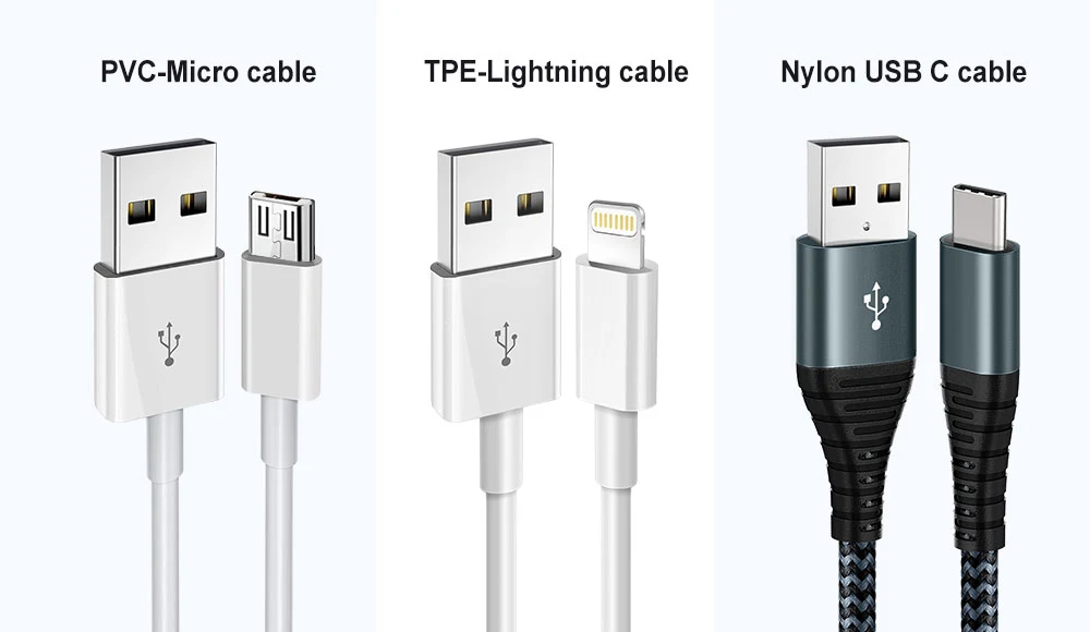
I hope this event will allow you to experience and purchase it yourself at a very low price. Disassemble our ordinary nylon braided USB C cable to evaluate our rigor of USB C pin wiring. If you have custom transmission needs for a USB C cable, but are not sure how to connect the pins. Please contact us, our experienced team of engineers is fully capable of configuring the corresponding pin wiring method according to your needs.
In this article, we have explored the usb c connector pinout, unraveling the various pins and their functions. The type c usb pinout is a crucial aspect to understand when working with USB-C cables and devices, as it determines the capabilities and functionalities of the connector.
Visit Apphone.com today to explore the latest USB-C solutions and elevate your digital connectivity experience. Your journey into the world of usb-c pinouts has never been more promising, thanks to the innovations and quality that Apphone consistently delivers. Choose us for a superior connection.
Customers can trust our expertise. Contact us here for inquiries and communication.
Why do 24-Pin USB Connectors Use 16-Core Wire?
The use of 16-core wire in 24-pin USB connectors may seem puzzling, but it’s primarily due to the versatility and future-proofing of USB Type-C connectors. While a USB Type-C connector physically has 24 pins, not all of them are used in all situations. The extra pins accommodate various functionalities, including high-speed data transfer, power delivery, alternate modes, and more. By using 16-core wire, manufacturers can ensure that they have enough conductors to handle these diverse functions while also leaving room for future enhancements. This flexibility allows USB Type-C to support an array of devices and applications, making it a truly universal connector.
How Are the Core Wires Soldered to the USB-C Connector?
Soldering the core wires to a USB-C connector is a precise and delicate process. The usb-c connector pinout has multiple pins in a small space, and each pin serves a specific function, such as data transmission, power delivery, or ground. To solder the core wires, each wire corresponding to a specific pin must be carefully aligned and attached to the corresponding pin on the connector. This requires specialized equipment and skilled assembly, as misalignment or incorrect soldering can lead to connection issues or damage to the connector. Manufacturing facilities use automated machinery or skilled technicians to ensure the precise attachment of core wires to USB-C connectors. At APPHONE we excel in the precise soldering of core wires to USB-C connectors. With reliable processes and skilled personnel, we ensure seamless and dependable connections. Trust APPHONE for high-quality manufacturing and initiate communication inquiries with confidence.
What is Common USB-C Manufacturing Terminology?
Here are some common USB-C manufacturing terminology;
- Surface Mount Technology (SMT): This is the process of attaching electronic components to the surface of a printed circuit board (PCB). USB-C connectors are often mounted onto PCBs using SMT.
- Reflow Soldering: Reflow soldering involves melting solder to attach components to a PCB. This is a common method used in USB-C manufacturing to ensure secure connections.
- Wave Soldering: Wave soldering is an alternative soldering method where a wave of molten solder is used to solder through-hole components, which may be used in some USB-C connectors.
- Quality Control (QC): USB-C manufacturing involves rigorous quality control processes to ensure that connectors meet industry standards and specifications.
- Alternate Modes:USB-C supports various alternate modes, such as DisplayPort and Thunderbolt. Manufacturing may involve configuring USB-C connectors to enable these modes.
- Thermal Management:Managing heat is essential in USB-C manufacturing, especially when dealing with high-power applications, such as laptops and smartphones. Proper heat dissipation mechanisms may be incorporated into the design.
- RoHS Compliance: USB-C manufacturing often adheres to the Restriction of Hazardous Substances (RoHS) directive, ensuring that connectors are free from certain hazardous materials.

Fast delivery
Fastest delivery within 22 days

Quick proofing
Fastest 3-day proofing cycle

After-sale protection
24-month long warranty

1V1Customer Service
Professional customer service follow-up

