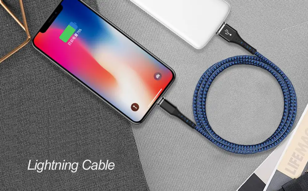
When most people look at a USB cable, they only see three things:
The connector
The cable jacket
The charging plug
However, hidden inside many modern USB-C, Lightning, and fast-charging cables is an important component that most users never notice:
PCB (Printed Circuit Board)
Although it is small enough to fit inside the connector shell, the PCB plays a critical role in modern charging cables.
In many high-performance cables, the PCB acts as a control center that helps manage:
Power transmission
Fast charging communication
Data transfer
E-Marker chip operation
Signal integrity
Safety protection
Without a properly designed PCB, many modern USB-C cables would not be able to support fast charging, high-speed data transmission, or intelligent power management.
In this article, we’ll explain what a PCB is, how it works inside a USB cable, and why it has become one of the most important components in modern charging cables.
What Is a PCB?
PCB stands for:
Printed Circuit Board
A PCB is a flat board made of insulating material and conductive copper traces.
Its purpose is to connect and support electronic components.
You can think of a PCB as:
The Road System of Electronics
Just as roads connect cities, PCB traces connect electronic components and allow electrical signals to travel where they need to go.
Without a PCB, electronic components would not be able to communicate efficiently.

Why Do USB Cables Need a PCB?
Years ago, charging cables were relatively simple.
Most cables only carried:
5V charging power
Basic USB 2.0 data
In those days, many cables did not require advanced circuitry.
Today, USB-C technology has become much more sophisticated.
Modern cables may support:
60W charging
100W charging
140W charging
240W charging
USB4
Thunderbolt 4
Thunderbolt 5
These advanced functions require intelligent control and communication.
That’s where the PCB becomes essential.
Where Is the PCB Located Inside a USB Cable?
In most USB-C cables, the PCB is located inside the connector housing.
The structure usually looks like this:
Connector Shell
↓
PCB Board
↓
E-Marker Chip
↓
Connector Pins
↓
Wire Core
Because space inside the connector is extremely limited, manufacturers often use:
Miniature PCBs
that are specially designed for compact applications.
What Does a PCB Do Inside a USB Cable?
Many people assume that the PCB simply connects wires.
In reality, it performs several important tasks.
1. Connecting Internal Components
The first function of the PCB is to provide organized electrical connections between:
Connector pins
Wire conductors
E-Marker chips
Control circuits
Without a PCB, these connections would be difficult to manufacture consistently.
2. Supporting Fast Charging Communication
Modern fast charging technologies require constant communication between:
The charger
The cable
The device
For example:
USB Power Delivery (PD)
PPS Fast Charging
Quick Charge
all rely on digital communication.
The PCB helps route these communication signals properly.

3. Hosting the E-Marker Chip
Many high-power USB-C cables contain:
E-Marker Chips
The E-Marker chip is usually mounted directly onto the PCB.
Together, they allow the cable to report:
Current capacity
Voltage capability
Charging specifications
Data transmission support
to connected devices.
4. Managing Signal Integrity
High-speed data standards such as:
USB 3.2
USB4
Thunderbolt
operate at extremely high frequencies.
At these speeds, signal quality becomes critical.
A well-designed PCB helps:
Maintain Signal Integrity
by reducing:
Signal loss
Crosstalk
Reflection
Electromagnetic interference
This helps ensure stable and accurate data transmission.

5. Supporting Safety Functions
Modern USB-C cables are expected to handle significant power levels.
Some cables now support:
240W USB-C Charging
At this power level, safety becomes extremely important.
The PCB can help support:
Overcurrent protection
Voltage monitoring
Communication verification
Safe power negotiation
These features help protect both the cable and connected devices.

Why PCB Quality Matters
Not all PCBs are manufactured equally.
The quality of the PCB directly affects cable performance.
Premium PCBs typically feature:
Precision copper traces
High-quality substrate materials
Better soldering quality
Improved electrical performance
Poor-quality PCBs may cause:
Charging instability
Data transfer errors
Connection failures
Excessive heat generation
What Materials Are Used in USB Cable PCBs?
Most USB cable PCBs are made using:
FR-4 Material
FR-4 is a fiberglass-reinforced epoxy laminate.
It offers:
Electrical insulation
Mechanical strength
Heat resistance
This makes it ideal for USB cable applications.
Copper Traces
Copper traces serve as the pathways that carry electrical signals.
High-quality PCBs often use thicker copper layers to improve conductivity and reliability.
How PCBs Help Enable 100W and 240W Charging
Modern USB Power Delivery standards require complex communication.
When a USB-C cable is connected:
The charger identifies the cable.
The PCB routes communication signals.
The E-Marker chip reports cable capabilities.
The charger adjusts output power.
Only after successful communication will the charger unlock higher power levels.
Without a properly designed PCB, this process would not work reliably.

PCB and Data Transfer Performance
A cable may look identical from the outside, but internal PCB design can significantly affect performance.
For example:
A premium USB4 cable may support:
40Gbps transmission
80Gbps transmission
while a low-quality cable may struggle to maintain stable signals.
PCB layout plays a major role in determining signal quality.
Why Cheap USB Cables Often Have Problems
To reduce costs, some manufacturers use:
Smaller PCBs
Thinner copper traces
Lower-quality materials
Poor soldering processes
As a result, users may experience:
Unstable charging
Slow data transfer
Frequent disconnections
Reduced cable lifespan
This is one reason premium cables typically cost more.
The Future of USB Cable PCB Technology
As USB technology continues to evolve, PCB designs will become even more advanced.
Future USB-C cables may support:
Higher charging power
Faster transmission speeds
Smarter communication systems
Improved thermal management
As these requirements increase, PCB technology will remain at the center of cable innovation.
Conclusion
Although it is hidden inside the connector, the:
PCB (Printed Circuit Board)
is one of the most important components in a modern USB cable.
It serves as the foundation for:
Fast charging communication
Data transmission
E-Marker chip operation
Signal management
Safety protection
Without a PCB, modern USB-C cables would not be able to deliver the charging speeds, data performance, and safety features that users expect today.
The next time you purchase a USB-C cable, remember that one tiny circuit board hidden inside the connector may be responsible for most of the cable’s intelligence and performance.


Fast delivery
Fastest delivery within 22 days

Quick proofing
Fastest 3-day proofing cycle

After-sale protection
24-month long warranty

1V1Customer Service
Professional customer service follow-up